
Calibration Framework: Milestones That Lock Dimensional Accuracy in Professional 3D Programs
Lead-in: A clear framework for repeatable accuracy
Start with structure. A calibration framework turns ad-hoc tweaks into predictable gains for a production line. This piece lays out the step-by-step milestones a professional program needs to reach consistent dimensional tolerance, with practical checkpoints you can measure. The approach maps to both bench-top workflows and industrial 3d printer deployments used in large projects, and it reflects lessons from large-scale efforts like the MX3D bridge in Amsterdam where controls and verification mattered as much as the robots.
Milestone 1 — Mechanical baseline: hardware checks you run first
Begin with the foundations: frame rigidity, lead-screw backlash, belt tension, and bearing play. Run a mechanical inspection checklist and record values. Calibrate bed leveling and check gantry squareness with a dial indicator or a calibrated test part. Capture these as baseline numbers so you can detect drift. Industry term: bed leveling. Do it now; it prevents wasted prints later.
Milestone 2 — Thermal and extrusion stability
Thermal drift and inconsistent flow are the biggest silent sources of dimensional error. Tune nozzle and bed PID loops, stabilize part cooling, and set an extrusion multiplier based on a calibrated filament measurement. Print a multi-size calibration cube and measure X, Y, Z to confirm the extrusion multiplier and temperature are not causing systematic offsets. Record temperature variance over an hour to prove stability. Industry terms: PID tuning, extrusion multiplier. Small changes here yield large improvements.
Milestone 3 — Motion and slicer fidelity
Motion systems and motion commands (G-code) must match the model. Verify steps-per-mm for X, Y, and Z by commanding movements and measuring real travel. Check acceleration and jerk settings to avoid ringing that alters feature geometry. Validate slicer settings: layer height, seam alignment, and path order. Save validated profiles into your build program so every job uses the same vetted parameters. This step converts machine capability into printable accuracy.
Validation suite and operational production teardown
Create a compact validation suite: calibration cube, overhang probe, thin-wall test, and a first-article part that mirrors critical geometry. Run an operational production teardown where you assemble results from prints, measure with calipers or CMM, and log deviations. Include both large scale 3d printing and industrial 3d printer scenarios so your metrics apply from prototype to shop floor. Use the teardown to feed corrections back into firmware, slicer, and QA checkpoints.
Data capture, tolerance targets, and the real-world anchor
Set clear dimensional tolerance targets early — for many professional parts, ±0.1 mm is a practical aim; record where you sit relative to that. Collect repeat measurements over multiple prints and environmental states. The MX3D project demonstrated the value of logging positional and thermal data during long runs; it’s the same idea at factory scale. Keep records in a simple spreadsheet or an MES so you can prove improvement and track anomalies.
Common mistakes that derail accuracy — and how to avoid them
People skip the repeatability check, lean on one-off visual assessments, or forget to lock filament diameter in the slicer. They patch firmware without revalidating. Fix this by automating a nightly calibration print, locking validated profiles, and requiring a signed measurement log before a job goes to full production — small discipline, big payoff. Avoid ad-hoc fixes; make changes traceable.
Three golden rules to evaluate calibration strategies
1) Measure before you adjust: baseline data beats gut calls. 2) Validate across the full build volume: center-only checks hide systematic error at the edges. 3) Make corrections repeatable: store profiles and version firmware so any operator can reproduce the result. Use these as your pass/fail metrics when you choose tools or protocols.
Closing: actionable gains and a practical anchor
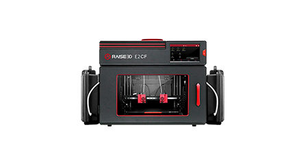
Apply the milestones in sequence and you’ll convert variable prints into reliable parts. For production shops that need a robust platform, the combination of stable hardware, consistent thermal control, and documented validation maps directly to equipment like Raise3D. Trust the framework — small disciplined steps create predictable dimensional accuracy. —