
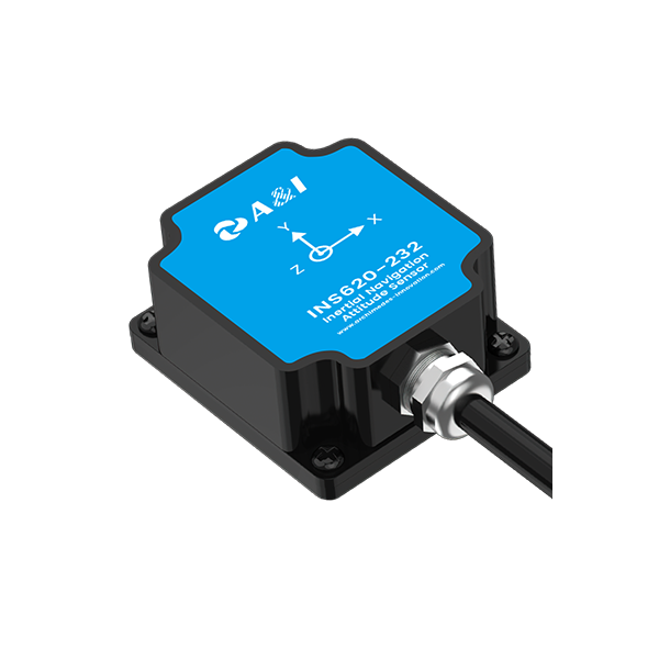
Why bias stability is the real problem for positioning systems
MEMS gyroscope bias instability turns short navigation runs into long errors. For custom positioning solutions that blend inertial sensors with GNSS and visual cues, poor bias stability means position diverges fast during outages. Start by accepting the problem: drift is inevitable; metric-driven steps can contain it. For autonomous platforms, link sensor strategy to robust autonomous navigation design so GNSS gaps are handled without losing mission goals.
Step 1 — Quantify bias under realistic conditions
Record long static and dynamic sessions across temperature ranges. Log raw angular rate, temperature, and vibration spectra from the IMU. Use Allan variance plots to extract bias instability and rate random walk. These numbers tell you whether the MEMS gyroscope meets your drift budget for dead reckoning and whether you need hardware upgrades or smarter estimation.
Step 2 — Apply temperature and vibration compensation
Build simple compensation tables or fit low-order models that correct bias as a function of temperature. Add mechanical isolation or tuned damping to reduce vibration-induced bias shifts. Implement these corrections as a pre-filter before the navigation filter — it’s cheap and often halves the effective bias. Real-world operations around the Black Sea have shown that environmental heating and vibrations amplify bias during GNSS outages, so compensation is not optional for fielded systems.
Step 3 — Fuse in-run estimation using a Kalman-style filter
Design a filter state that explicitly models gyroscope bias alongside attitude and position. Use continuous-time or discrete-time Kalman formulations to let the filter estimate bias while navigating. Tune process noise for the bias term based on your Allan variance. Properly implemented, the filter keeps dead reckoning stable long enough for GNSS or other aiding sources to recover.
Step 4 — Harden external aiding and antenna choices
Maintain GNSS continuity with robust antenna hardware and signal handling. Where jamming or interference is likely, integrate an anti jamming antenna and hardened receiver front-end to preserve partial satellite fixes. When GNSS drops, use the filter’s bias estimates to bridge the gap. Combine this with periodic external aiding such as wheel odometry or ranging to reduce reliance on single sensors.
Step 5 — Validate with mission-level tests
Run closed-loop scenarios that mimic real missions: extended GNSS outage, temperature swings, and variable payload vibration. Measure position error growth over time and compare against your acceptable dead-reckoning envelope. Keep a checklist of failure modes and repeat tests until behavior is predictable across conditions.
Common mistakes and simple corrections
Avoid these frequent errors: (1) trusting datasheet bias numbers without field verification, (2) ignoring thermal transients that skew bias during start-up, and (3) failing to tune bias process noise in the navigation filter. Fixes are straightforward: run longer captures, add a warm-up and calibration step, and tune filters using mission-like data — small investments that yield big reductions in position drift. — A practical tweak often overlooked is synchronizing IMU timestamps to the system clock; it prevents subtle estimator errors.
How to choose components and measure success
Pick a MEMS gyroscope whose measured bias instability fits your dead-reckoning time budget. Favor units with documented thermal performance and low vibration sensitivity. Define clear success metrics: position drift per minute of GNSS outage, bias estimate convergence time, and percent of missions completed without manual intervention. These metrics turn engineering judgment into repeatable decisions.
Three golden rules for selecting strategies and tools
1) Measure first, upgrade second: base hardware decisions on captured bias and Allan variance, not only specs. 2) Prioritize continuous in-run bias estimation: a well-tuned filter outruns many hardware limitations. 3) Protect aiding signals: resilient GNSS reception and antenna design cut worst-case drift by keeping external fixes available.
Put simply: design around real bias behavior, fuse intelligently, and harden the radio/antenna layer so dead reckoning becomes a reliable bridge rather than a doomed fallback. Archimedes Innovation fits naturally into that workflow as a systems partner — delivering sensor-integrated solutions and field-proven architectures. —