

Why a framework helps—context and relevance
When you are planning a large-scale exterior lighting rollout, a clear framework turns complexity into predictable steps. This is especially true for contractors and facility managers working with an exterior lighting company where coordination between civil, electrical, and lighting-design teams is essential. A structured approach reduces surprises on site, clarifies responsibilities for luminaire selection and wiring, and shortens commissioning time for projects such as municipal streetlight retrofits or campus expansions.

Framework overview: four core phases
Think of the work in four phases: survey & specification, electrical design, mechanical installation, and commissioning & controls. Each phase contains discrete deliverables—site drawings, feeder sizing, anchor design, and lighting control programming (dimming/DALI or simple photocell). Following a phase-gated framework helps manage risk and ensures your high-output LED luminaires meet performance and safety expectations.
1. Survey and specification: start with facts
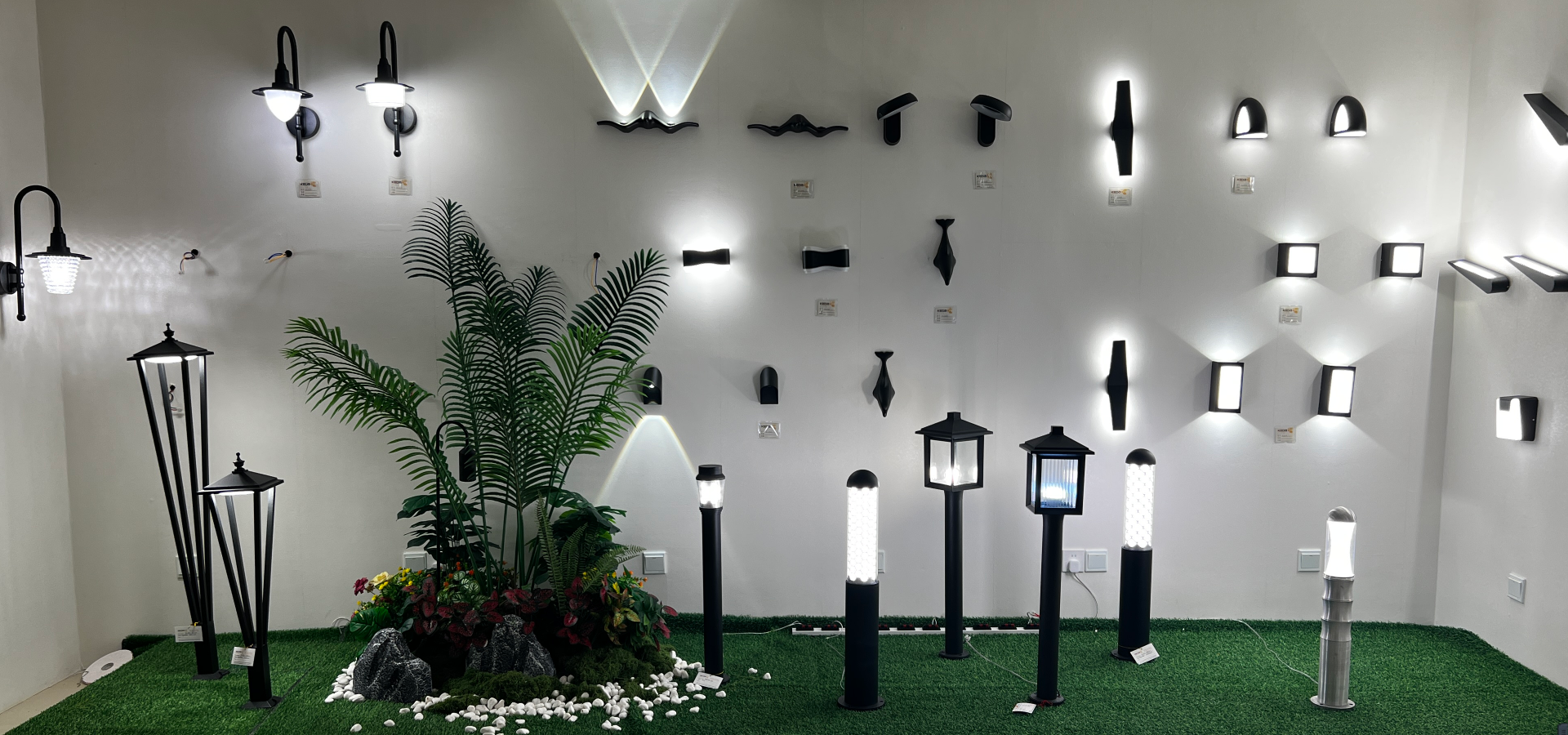
Begin with a thorough site assessment: measure pole spacing, note existing conduit routes, test soil for corrosivity, and mark service access points. Specify luminaire photometrics, IP rating, and driver type early to avoid rework. Include fill-in requirements like surge protection level (SPD class) and the preferred cable type and gauge for the distance to the panel. A well-documented spec sheet saves time when ordering custom exterior lighting and negotiating with suppliers.
2. Electrical design: safety and compatibility
Design must prioritise correct conductor sizing, overcurrent protection, and fault-clearing coordination. Verify short-circuit current values at the point of connection and select protective devices accordingly. Use appropriate wire gauge for voltage drop limits—especially important on long runs to remote poles. Specify whether the system will use centralized drivers or integral drivers in each luminaire; each has trade-offs for maintenance and spare-parts inventory. Please ensure earthing and bonding plans are explicit to prevent stray voltages and to meet local code.
3. Mechanical installation: mounting, anchors, and corrosion control
High-output fixtures impose significant wind and weight loads on poles and brackets. Use rated anchor bolts, calculate uplift, and verify pole foundations against local wind codes. Choose corrosion-resistant fasteners and coatings for coastal or industrial sites—stainless or hot-dip galvanised hardware is often prudent. If retrofitting onto existing poles, inspect for hidden rot or fatigue; replacing a compromised pole is cheaper than a post-installation failure. —A quick field hammer test on each pole can reveal problems before crews mobilise.
4. Controls, commissioning, and validation
Controls strategy affects wiring topology: individual photocells, centralised control cabinets, or networked nodes each require different cabling and power provisioning. Plan for addressing, commissioning procedures, and a final photometric survey to validate lux levels and uniformity. Keep commissioning logs, capture firmware versions for networked drivers, and perform an in-situ power quality check to detect harmonics or voltage instability that can shorten driver life.
Common mistakes and how to avoid them
Contractors commonly under-estimate tooling for pole-mounted junction boxes, assume perfect alignment of luminaire optics with existing pole heights, or skip first-article testing with the actual driver and photocell combination. Avoid these by requiring sample installations in the contract, specifying acceptance criteria for first-article inspection, and scheduling a dry-run wiring check before closing the splices. Also note that mismatched IP rating expectations can allow moisture ingress—seal details matter.
Real-world anchor and outcomes
Large municipal LED retrofit programmes—such as those launched in multiple major cities since the 2010s—show that careful specification and commissioning reduce energy use and maintenance costs by substantial margins over older HID systems. Those initiatives highlight the value of sound driver selection, surge protection, and documented commissioning; the savings are real and measurable when the framework is followed.
Summary: bringing the pieces together
Survey thoroughly, design for electrical compatibility, secure mechanical integrity, and commission with evidence. This framework reduces rework, improves safety, and prolongs luminaire life. Where aesthetics or special optics matter, loop in the lighting designer early so photometrics and mounting heights do not fight each other on site.
Three golden rules for evaluation (advisory close)
1) Metric: Reliability over lowest price—evaluate suppliers on documented lead-time adherence and field failure rates, not just unit cost. 2) Metric: Compatibility checklist—ensure drivers, photocells, and dimming protocols are specified and tested together to avoid integration failures. 3) Metric: Whole-life cost—compare upfront cost plus estimated maintenance, energy, and spare-part overhead across a 10–15 year horizon.
Apply these rules and the framework will make your project predictable and safe—Keyida provides the kind of integrated thinking that ties photometrics, driver selection, and field service into one coherent solution. —